一、端口聚合
指将多个物理端口汇聚在一起,形成一个逻辑端口,以实现流量吞吐量在各成员端口的负荷分担,设备根据用户配置的端口负荷分担策略决定网络封包从哪个成员端口发送到对端的设备。当设备检测到其中一个成员端口的链路发生故障时,就停止在此端口上发送封包,并根据负荷分担策略在剩下的链路中重新计算报文的发送端口,故障端口恢复后再次担任收发端口。链路聚合在增加链路带宽、实现链路传输弹性和工程冗余等方面是一项很重要的技术。
1、端口聚合模式
802.3ad IEEE 802.3ad Dynamic link aggregation (Default)
active-backup Fault tolerant: only one slave in the bond is active
broadcast Fault tolerant: transmits everything on all slave interfaces
round-robin Load balance: transmit packets in sequential order
transmit-load-balance Load balance: adapts based on transmit load and speed
adaptive-load-balance Load balance: adapts based on transmit and receive plus ARP
xor-hash Load balance: distribute based on MAC address
2、端口聚合示例
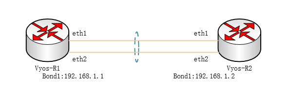
R1配置
vyos@R1# set interfaces bonding bond1 address 192.168.1.1/24    //创建端口绑定并设置绑定接口IP地址
vyos@R1# set interfaces bonding bond1 description “To Vyos-R2”  //设置此绑定接口的描述
vyos@R1# set interfaces bonding bond1 mode 802.3ad      //设置端口聚合模式默认:802.3ad(lacp)
vyos@R1# set interfaces ethernet eth1 bond-group bond1      //物理端口加入绑定端口(旧版本)
vyos@R1# set interfaces ethernet eth2 bond-group bond1      //物理端口加入绑定端口(旧版本)
vyos@R1# set interfaces bonding bond1 member interface eth0     //物理端口加入绑定端口(新版本)
vyos@R1# set interfaces bonding bond1 member interface eth1     //物理端口加入绑定端口(新版本)
注:“将物理端口加入绑定端口”新旧系统版本操作方式不同。
R2配置
vyos@R2# set interfaces bonding bond1 address 192.168.1.2/24 //创建端口绑定并设置绑定接口IP地址
vyos@R2# set interfaces bonding bond1 description “To Vyos-R1” //设置此绑定接口的描述
vyos@R2# set interfaces bonding bond1 mode 802.3ad //设置端口聚合模式默认:802.3ad(lacp)
vyos@R2# set interfaces ethernet eth1 bond-group bond1 //物理端口加入绑定端口(旧版本)
vyos@R2# set interfaces ethernet eth2 bond-group bond1 //物理端口加入绑定端口(旧版本)
vyos@R2# set interfaces bonding bond1 member interface eth0 //物理端口加入绑定端口(新版本)
vyos@R2# set interfaces bonding bond1 member interface eth1 //物理端口加入绑定端口(新版本)
注:“将物理端口加入绑定端口”新旧系统版本操作方式不同。
查看
vyos@vyos:~$ show interfaces bonding bond1 slaves       \\查看绑定成员端口
Interface       RX: bytes   packets     TX: bytes       packets
bond1                0           0       182060         4324
eth0                260          2       182996         4332
eth1                346          3       936             8
vyos@vyos:~$ show interfaces bonding bond1      \\查看绑定接口详细信息
bond1: <BROADCAST,MULTICAST,MASTER,UP,LOWER_UP> mtu 1500 qdisc noqueue state UP group default qlen 1000
    link/ether 50:00:00:01:00:00 brd ff:ff:ff:ff:ff:ff
    inet 192.168.1.1/24 brd 192.168.1.255 scope global bond1
        valid_lft forever preferred_lft forever
    inet6 fe80::5200:ff:fe01:0/64 scope link
        valid_lft forever preferred_lft forever

    RX:     bytes   packets  errors  dropped    overrun      mcast
                0        0       0       0           0          0
    TX:     bytes   packets  errors  dropped    carrier      collisions
            182060      4324    0        0           0          0
vyos@vyos:~$
二、网桥
网桥工作在OSI模型中数据链路层,和交换机类似,可隔离冲突域。在vyos中创建网桥可将物理接口组成逻辑交换机使用。
1、命令格式
#set interfaces bridge <”bridge name”> //创建网桥
#set interfaces bridge <”bridge name”> address <address | dhcp | dhcpv6> //配置桥上IP地址
#set interfaces bridge <”bridge name“> description <description> //配置网桥描述
#set interfaces bridge <”bridge name”> member interface <member> //加入成员接口
2、实验
- 要求:按照拓扑标记,实现三台PC可以互通。
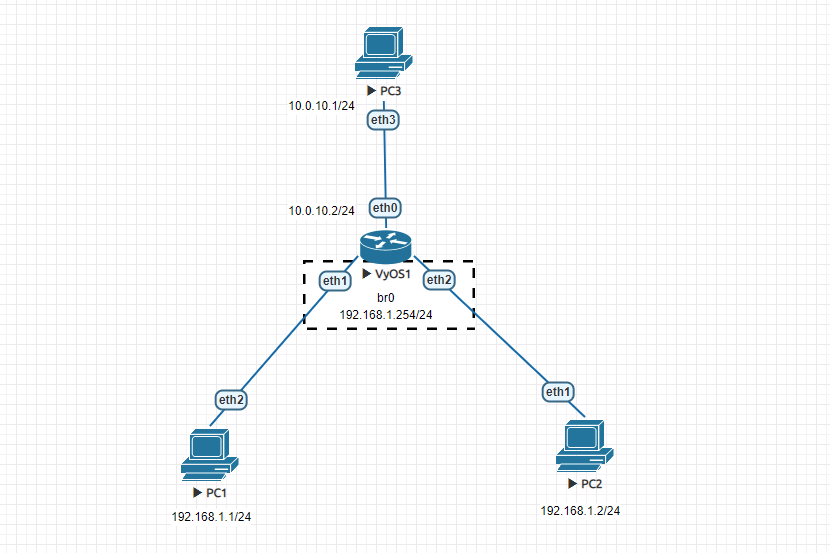
- 分析:通过拓扑可以得到,PC1和PC2在同一网段,两者通信只需二层互通就行,所以需要在vyos1中创建网桥实现二层交换。PC1、PC2与PC3互通需要进行3层转发,3层转发需要路由条目,所以需要在三台PC上配置静态路由,则br0是PC1、PC2的下一跳,故需要在br0上配置IP地址。
- 操作步骤:
PC1命令
vyos@PC1# set interfaces ethernet eth2 address 192.168.1.1/24 //设置IP地址
vyos@PC1# set protocols static route 0.0.0.0/0 next-hop 192.168.1.254 //设置网关

PC2命令
vyos@PC2# set interfaces ethernet eth1 address 192.168.1.2/24 //设置IP地址
vyos@PC2# set protocols static route 0.0.0.0/0 next-hop 192.168.1.254 //设置网关

PC3命令
vyos@PC3# set interfaces ethernet eth3 address 10.0.10.1/24 //设置IP地址
vyos@PC3#set protocols static route 192.168.1.0/24 next-hop 10.0.10.2 设置去往192.168.1.0/24网段的静态路由

Vyos1命令
vyos@vyos1# set interfaces bridge br0 address 192.168.1.254/24 //设置网桥IP地址作为下面PC的网关
vyos@vyos1# set interfaces bridge br0 member interface eth1 //把eth1加入网桥
vyos@vyos1# set interfaces bridge br0 member interface eth2 //把eth2加入网桥
vyos@vyos1# set interfaces ethernet eth0 address 10.0.10.2/24 //设置IP地址
三、STP
生成树协议主要是避免二层环路引起的广播风暴。当环境中出现环路时,会根据生成树规则阻断接口,以避免遭成二层广播风暴影响业务流量。同时在设计网络的时候利用生成树特性可以对活动链路发生故障是提供容错的备份链路。因为在二层链路才会出现环路,所以Vyos生成树协议是开在网桥上。
1、命令格式
vyos@vyos# set interfaces bridge br0 stp    //网桥上启用生成树协议
vyos@vyos:~$ show bridge br0 spanning-tree  //查看生成树信息
四、VLAN
虚拟局域网(Vitrual Local Area Network简写VLAN)是一种局域网交换技术,网络管理员可以借用该技术,将网络进行逻辑区域划分,以减少广播域规模。同时也可以根据网络作用、位置、部门进行区域划分,配合防火墙规则或者ACL策略管理各个区域的互联互通。
VLAN技术实现非常灵活,它不受用户物理位置的限制,根据用户需求进行划分;可在同一交换机上实现,也可跨交换机实现;
VLAN技术属于OSI数据链路层技术,每个VLAN就相当一个网段,不同VLAN间通信必须经过L3路由完成。常见VLAN间通信一般采用,三层交换或者单臂路由。
一、网桥模式
网桥模式是基于二层虚拟网桥划分,类似Huawei交换机中vlan划分,可设置Vlanif、trunk接口、access 接口。
1、命令格式
#set interfaces bridge <”bridge name“> vif <vlan-id> address <address | dhcp | dhcpv6> //设置vlan虚拟接口IP地址,类似huawei中vlanif;
#set interfaces bridge <”bridge name“> vif <vlan-id> description <description> //设置vlan虚拟接口描述;
#set interfaces bridge <”bridge name“> member interface <member> native-vlan <vlan-id> //设置物理口所属vlan ,access模式;
#set interfaces bridge <”bridge name“> member interface <member> allowed-vlan <vlan-id> //设置接口为trunk模式,并设置trunk接口所允许的vlan流量;
2、实验
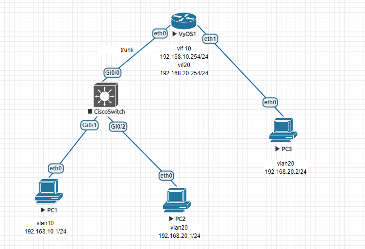
- 要求:按照拓扑标记,通过网桥模式划分vlan,实现三台PC互通
- 操作步骤:
Vyos1配置
vyos@vyos1#set interfaces bridge br0 member interface eth0 allowed-vlan 10
vyos@vyos1#set interfaces bridge br0 member interface eth0 allowed-vlan 20
vyos@vyos1#set interfaces bridge br0 member interface eth1 native-vlan 20
vyos@vyos1#set interfaces bridge br0 vif 10 address 192.168.10.254/24
vyos@vyos1#set interfaces bridge br0 vif 20 address 192.168.20.254/24

Cisco Switch配置
interface GigabitEthernet0/0
switchport trunk encapsulation dot1q
switchport mode trunk
interface GigabitEthernet0/1
switchport access vlan 10
switchport mode access
!
interface GigabitEthernet0/2
switchport access vlan 20
switchport mode access

PC1配置
vyos@PC1#set interfaces ethernet eth0 address 192.168.10.1/24
vyos@PC1#set protocols static route 0.0.0.0/0 next-hop 192.168.10.254

PC2配置
vyos@PC2#set interfaces ethernet eth6 address 192.168.20.1/24
vyos@PC2#set protocols static route 0.0.0.0/0 next-hop 192.168.20.254

PC3配置
vyos@PC3#set interfaces ethernet eth4 address 192.168.20.2/24
vyos@PC3#set protocols static route 0.0.0.0/0 next-hop 192.168.20.254
- 总结:通过实验PC1和PC2互通说明,vyos可以实现跨vlan3层通信;PC2和PC3互通说明,同一vlan可以跨设备通信;
二、子接口模式
在vyos中划分vlan的另一种形式就是在子接口下。子接口模式在单臂路由实例中比较常见,路由器可以借助子接口再配合vlan交换机可变相增加路由器接口。单臂路由也可以把划分vlan的交换机通过路由器子接口实现vlan间通信。
1、命令格式
#set interfaces ethernet <interface> vif <vlan-id> //创建以vlanID命名的子接口
#set interfaces ethernet <interface> vif <vlan-id> address <address | dhcp | dhcpv6> //子接口上设置IP
#set interfaces ethernet <interface> vif <vlan-id> description <description> //添加子接口描述
2、实验
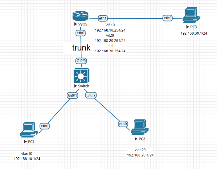
- 要求:按照拓扑标记,通过子接口模式划分vlan,实现三台PC互通
- 操作步骤:
Vyos配置
vyos@vyos#set interfaces ethernet eth0 vif 10 address 192.168.10.254/24
vyos@vyos#set interfaces ethernet eth0 vif 20 address 192.168.20.254/24
vyos@vyos#set interfaces ethernet eth1 address 192.168.30.254/24

Switch配置
interface GigabitEthernet0/0
switchport trunk encapsulation dot1q
switchport mode trunk
!
interface GigabitEthernet0/1
switchport access vlan 10
switchport mode access
!
interface GigabitEthernet0/2
switchport access vlan 20
switchport mode access

PC1配置
vyos@PC1#set interfaces ethernet eth0 address 192.168.10.1/24
vyos@PC1#set protocols static route 0.0.0.0/0 next-hop 192.168.10.254

PC2配置
vyos@PC2#set interfaces ethernet eth0 address 192.168.20.1/24
vyos@PC2#set protocols static route 0.0.0.0/0 next-hop 192.168.20.254

PC3配置
vyos@PC3#set interfaces ethernet eth0 address 192.168.30.1/24
vyos@PC3#set protocols static route 0.0.0.0/0 next-hop 192.168.30.254
五、端口镜像
众所周知,在利用抓包工具抓包时,默认情况只有在同一个冲突域中才能抓到其他机器相互通信的数据包,非同一个冲突域中,只能抓到广播、组播、交换机泛洪等数据包。在流量审计(例如:IDS、行为审计)中也会遇到同样问题。针对上述问题可以利用vyos端口镜像功能,将源端口流量镜像到目标端口,在目标端口连接审计设备或诊断工具即可分析流量。
1、命令格式
#set interfaces ethernet <interface> mirror <interface>
2、实验
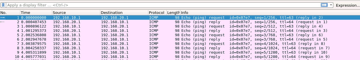
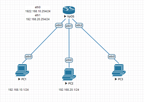
- 要求:按照拓扑标记,PC3可以获取到PC1和PC2相互通信的数据包
- 操作步骤
Vyos
vyos@vyos#set interfaces ethernet eth0 address 192.168.10.254/24  //设置eth0 IP地址
vyos@vyos#set interfaces ethernet eth1 address 192.168.20.254/24  //设置eth1 IP地址
vyos@vyos#set interfaces ethernet eth1 mirror egress eth2     //将eth1出向流量镜像到eth2
vyos@vyos#set interfaces ethernet eth1 mirror ingress eth2    //将eth1入向流量镜像到eth2

PC1
vyos@PC1#set interfaces ethernet eth0 address 192.168.10.1/24     //设置IP
vyos@PC1#set protocols static route 0.0.0.0/0 next-hop 192.168.10.254       //设置网关

PC2
vyos@PC2#set interfaces ethernet eth0 address 192.168.20.1/24     //设置IP
vyos@PC2#set protocols static route 0.0.0.0/0 next-hop 192.168.20.254       //设置网关
PC3抓包